
by Mark Davidson
The ignition system of an automobile generates and delivers the spark, used to ignite the air/fuel mixture inside the combustion chamber. The spark must be delivered at an exact time, in the proper sequence and of sufficient duration for the engine to run correctly. In addition, extremely high voltage is needed for the spark to bridge the gap of the spark plug in the harsh environment of the combustion chamber.
Prior to the early 70's, breaker point ignition systems were used on all vehicles and this allowed for simple automotive diagnosis, troubleshooting, and auto repair. Breaker point ignition systems adequately met ignition requirements for decades, until the invention of stricter automotive emission control requirements. In order to meet lower emission standards, passenger car and light truck manufacturers were forced to use leaner air/ fuel mixtures. The voltage required to ignite a lean air/fuel mixture could not be economically provided by the breaker point system. So as a result, electronic ignition systems were developed to furnish the high voltage spark necessary to ignite the lean air/fuel mixture.
The components used in the breaker point system consisted of a distributor, ignition points, condensor and ignition coil. The ignition coil contains two circuits, the primary circuit and the secondary circuit. Switched ignition voltage is supplied to the positive side of the ignition coil primary circuit. The current path flows through the ignition coil to the distributor, where it is grounded by the ignition breaker points. The ignition points are placed in the distributor adjacent to a cam mounted on the distributor shaft. When the engine is running, the spinning cam opens and closes the contacts of the points hundreds of times per second. When the points are closed, current flow is allowed through the primary circuit and a large magnetic field is created inside the ignition coil. The time that the ignition points are closed, is referred to as coil saturation time. Coil saturation is the amount of electrical current that builds up inside the primary coil windings. The greater the saturation, the larger the voltage output of the ignition coil. When the points are opened by the distributor cam, the magnetic field is caused to collapse and high voltage is generated inside the ignition coil. This current is referred to as secondary ignition voltage. The maximum secondary voltage output is around 20,000 volts. The current path of secondary voltage is through the coil wire into the distributor cap, across the rotor and out of the distributor cap, through the plug wires to the spark plugs.
The breaker point system suffers many disadvantages, one is the longevity of the ignition points. In order to provide an acceptable length of service, the maximum amount of current that can flow through the ignition points is around 4 amps. This limitation directly affects the maximum secondary voltage output of the ignition coil by reducing the amount of coil saturation. Another drawback is the limitations placed on the system at high engine speeds. When the engine is at high speed, the points open and close so rapidly that coil saturation is inadequate. The points are closed for too short a duration to allow sufficient current to flow through the primary circuit. This causes a reduction in secondary ignition voltage output at higher engine speeds. Another phenomenon affecting breaker point ignition systems, is the tendency of the points to bounce or float, at high engine speeds. This can affect the timing of spark delivery to the spark plugs and have an adverse affect on engine operation. Finally, breaker point ignition systems require frequent maintenance to ensure the correct operation of the ignition system. Because ignition points are subject to wear by friction and current flow, their replacement or adjustment during auto repair is required at regular intervals.
The development of the electronic ignition system allowed automotive engineers to re-design the ignition system components to generate higher secondary ignition voltage. Transistors were used to switch the primary ignition current instead of mechanical ignition points, so the amount of primary current was increased. This allowed higher secondary voltage above 40,000 volts on some engines. The ignition coils were re-designed for faster saturation times so that the secondary ignition voltage fall off, at high engine speeds, was reduced. Transistorized ignition reduced vehicle maintenance by the elimination of the ignition points from the primary ignition system.
With the conventional automotive electronic ignition system, the points have been replaced with a signal device mounted inside the distributor. The signaling device, either a magnetic pulse generator or a hall effect switch, controls the switching of a transistor in the engine control module. The transistor is used to switch the automotive ignition coil primary circuit on and off. When the engine is first started, ignition timing is under direction of the ignition control module; take special note of this before embarking on a automotive troubleshooting and repair venture. When the engine reaches a predetermined engine speed, ignition timing control is then managed by the engine control module. The engine control module modifies the signals to the transistors inside the control module to vary ignition timing, based on engine operating conditions.
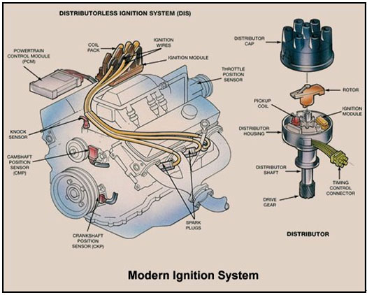
Most late model automobiles now use distributorless ignition systems. The distributorless ignition system provides higher secondary voltages, more efficient operation and lower maintenance, in comparison with conventional electronic ignition systems.
With distributorless ignition systems, ignition timing and firing order is managed by the engine control module. The engine control module determines cylinder position based on inputs from the crankshaft sensor, and in some designs, the camshaft position sensor. The engine control module reads this information, and operates the primary ignition circuit of each coil, in sequence, using the ignition control module.
The waste spark distributorless ignition system is used on most vehicles. The system matches paired cylinders to one coil. These cylinders are referred to as buddy cylinders, since they are always in the same position, relative to the crankshaft. When one buddy cylinder is at top dead center, the other is also at top dead center. However, one cylinder will be on the compression stroke, while the other is on the exhaust stroke. The ignition coil will deliver spark to both cylinders at the same time when they reach top dead center. Since one cylinder will be on the exhaust stroke, the spark delivered to that cylinder is not used for combustion, this is known as the waste cylinder. Since the energy required to allow the spark to bridge the gap of the waste cylinder are very low, a majority of the secondary voltage is used to fire the spark plug of the active cylinder.
Another type of distributorless ignition system is the direct ignition system. The direct ignition system uses one ignition coil per spark plug. Most systems use an ignition driver module to control the primary ignition circuit. Individual coil primary current flow is operated by signals from the engine control module to the ignition driver module. The engine control module determines spark timing based on input information from the crankshaft and the camshaft position sensors.
» More Information 


